Fixing a bricked pc, the tryharder way
Intro
My friend managed to brick his notebook while removing linux and reinstalling windows.
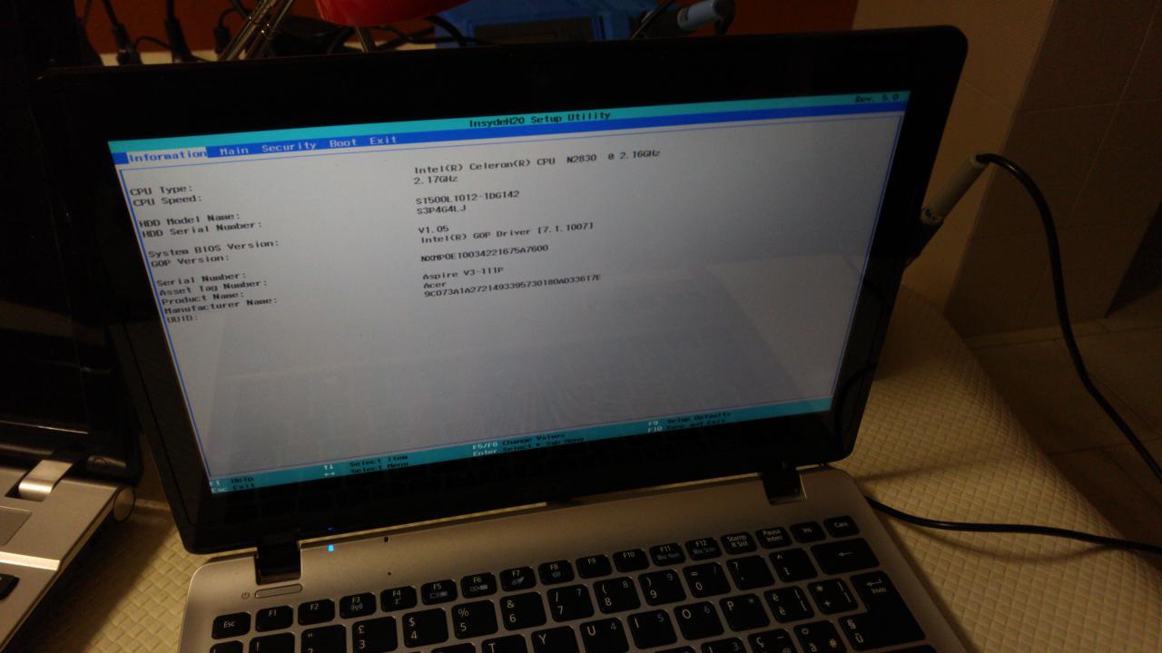
The model is: Acer Aspire V 11 Touch - V3-111P-C7WC
Motherboard: DA0ZHJMB6E0 (REV E)
I’m not sure how he did this… he remember that he probably turned on “fast boot” before erasing the disk.
Usually this is not a problem and doesn’t brick a pc, you open the bios and change boot priority in order to boot from usb/cd and reinstall.
But bios wasn’t accessible and the computer just said “nothing bootable”
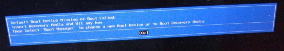
if you press ok it will say: what do you want to boot? ubuntu, grub, kali.
You select any of these you will hear the hdd spinning for a moment and it will say again “nothing bootable”.
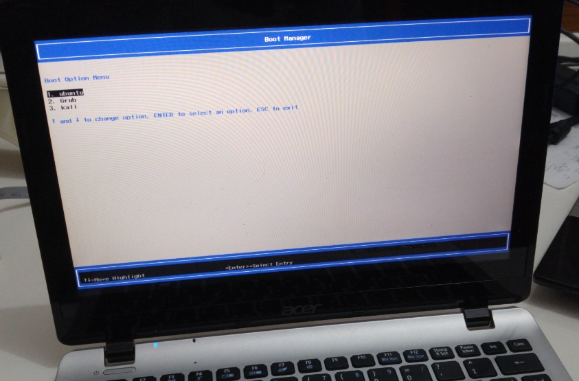
That is, pc bricked.
At the beginning we tried the usual basic stuff:
- F2 which is the typical hotkey to open bios on acer computers (confirmed by the user guide from official website) but it wasn’t working… the only effect was that the screen stayed black until you stopped spamming F2.
The acer logo wasn’t even shown on boot which is strange and the first visible thing was the error message.
Some people on the internet say that if you have fastboot enabled keyboard is not initialized so you can go bios only by asking the OS to reboot in bios.
But what if there is no OS or it doesn’t boot?
Some other say that the time to go in bios is super short but if you are fast enough you can get into it. - We tried F12 which is the typical “boot menu” key.
- We tried almost every key: Del, Esc, F2, F10, any F key, combinations of shift/alt/ctrl…
- We tried also an external usb keyboard (maybe F2 was just broken?)
- We tried to search a “clear cmos” jumper but there wasn’t any
- We removed the notebook battery and internal battery in the hope that this will clear the memory with no success
- We tried an usb cd reader as this model has not an internal cd reader again without success.
This because usually cd have higher boot priority, and floppy even higher.
We haven’t tried floppy as we don’t have any floppy or floppy reader. - We tried the “phoenix crisis disk”, it adds the necessary files on usb key and we booted while holding fn+esc or fn+f (depends on the model) but there was no visible/useful effect (power led was blinking).
We made many tests using different bios file names: “bios”, “bios.wph”, …
After several tests, when we set the correct bios file name “ZHJ.FD” (which was the original name from the downloaded bios upgrade), the power led started blinking “differently”. We hoped that it was reflashing the bios but the usb key led was not indicating any activity and in fact nothing happened. - We did not have a debug card, i have found a schematic online but it was for ISA BUS (desktop pc).
If you are interested: Build your own P.O.S.T. card - We also tried to install ubuntu into the notebook HDD from another pc since it doesn’t take much effort, but as expected ubuntu wasn’t seen/booted by the pc (more on this later).
At this point it was clear that we could not open the bios or boot anything…
Now a normal person call the assistance or buy a new pc but…
I could not accept this! it obviously works as to show that error it MUST work! CPU, RAM, BIOS itself, keyboard, video card, monitor, hdd, every component was working otherwise we couldn’t have that error displayed!
Time to tryharder - Challenge acceped
My idea was to dump the bios, read the boot partition UUID from the bios and set it on the hard disk partition so that it would boot ubuntu as if it was never deleted.
This is necessary because while old-style MBR based partition table uses the first sector as partitions index, have max four partitions and use a bootable flag on the partition entry to say what is bootable.
GPT (GUID Partition Table) support many more partitions and have an UUID that identify them.
It is not enough to reinstall ubuntu from another pc and plug the disk, the UUID will be different since it is a random number for each partition.
That boot UUID was stored in the bios flash chip as the boot menu with ubuntu, grub, kali, was visible even with the hdd not present.
My pc for example (again acer) behave differently: if you remove the disk, the uefi entry is deleted and there is no bios menu to add them back.
Bios dump
Old notebook bios dump
I have dumped a bios some time ago from an old half-broken notebook to learn how to do it and to make a 3GHz carillon :)
It wasn’t very hard to dump it:
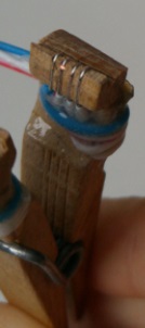
I desoldered the chip (W25X80) without caring much of the result/the mother board since the pc was broken anyway and made the pins longer as shown in the photo:
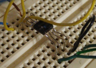
I than used this flashrom schematic and Arduino homemade code to dump the chip.
I also used a HEF4050B Hex non-inverting buffer to lower the voltage from 5V to 3,3V. The DO (data out pin) was connected directly to Arduino since 3,3V is enough to be interpreted as logic one.
Initial study
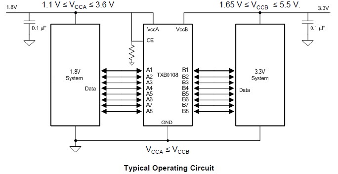
Unluckily this computer have a different chip: W25Q64FW that is rated 1,95V max so it’s a 1,8V logic.
- HEF4050B can’t be used as it’s min operating voltage is higher
- Output pin can’t be connected directly to Arduino, 1,8V is too low
After searching in internet I have found a useful chip that could solve my problem:
TXB0108 8-Bit Bidirectional Voltage-Level Translator
I only had to put this between the raspberry and the SPI Flash chip.
Gathering and making the necessary parts
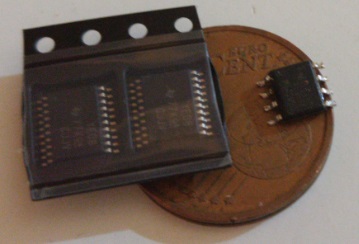
There are many of these voltage level shifter chips, so i mailed my local shop with a list of them. They mailed me “this one is available, it is small, for you it’s ok?” i watched the (low quality) photo and i thought that it was SMD, so that it was small but usable… Well it was TSSOP so it was even smaller:
Luckily i had recently finished building a CNC milling machine so this was the perfect use case.
In case you are interested in building one, there is an open source firmware for Arduino called GRBL
Here you can see an early layout of a “size adapter” PCB made with a super-advanced cad tool: Paint :)

Here is the finished layout and milling.
Actually the most left and right pins have been modified to keep the trace larger since it was possible:
You can see that the board is not perfect due to backslash, but considering that the cnc milling machine is hand-made and made of recycled wood: legs of the sofa, kitchen furniture door, bedroom shelf. The precision is far higher than expected.
I like making things in the MacGyver way.
The pins distance is 0,65mm and pin size is 0,3 mm leaving us 0,35mm of space between pins.
Also the cutter was not the correct one: size 3mm conical shape, but this is what the shop sold…
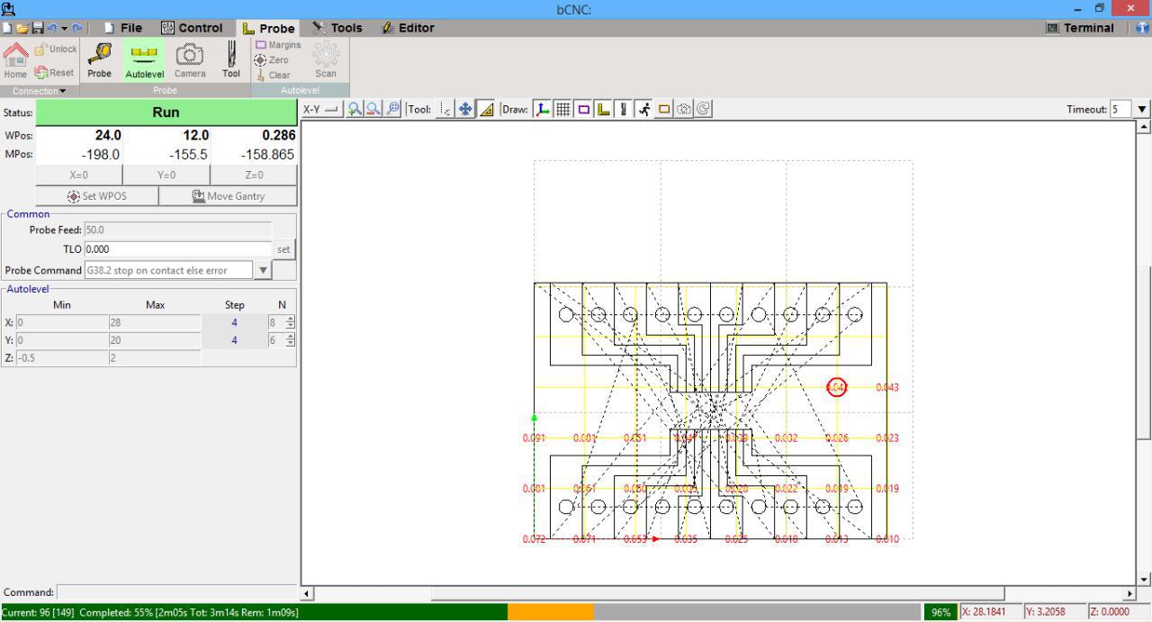
Autolevel played an important role.
Anyway for the next time a cylindrical one will do the job better.
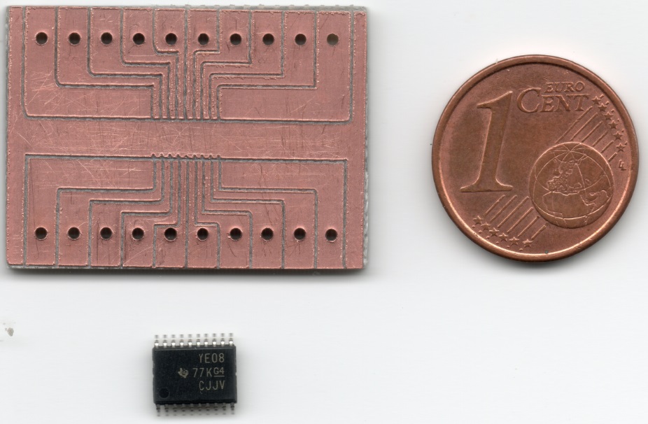
The chip is super small and not easy to solder, but in the end i managed to do it without short circuits, note also on the right the welding metal and it’s size which is quite bigger than chip pins.
Again this is what i had, but you should buy smaller one.
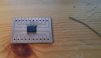
Now the first part was ready, i only needed a SOIC test clip, i could buy it or… make it!
Turns out that even if the wire positions were correct it wasn’t usable as without some force it wouldn’t stay in position and it could also shift left or right short circuiting everything.
I didn’t want to damage the pc or the chip so i decided to buy it on the internet since local shop didn’t have it :(
Here the nightmare begins… i have ordered it from Italy to Italy, actually 100km (1 hour distance) from home but it never arrived… since i was sure that it was lost somewhere a friend ordered another on amazon (this time with express courier), it arrived fast but it arrived wrong ‘-_- 8x8 instead of 4x4.
In the end the other arrived too one month later!!!! ‘-_- when it was too late and the pc was fixed.
Luckily on the notebook there was space so i resoldered wires and converted it to a 4x4 pin.
I also coded a python script for the raspberry that could help me managing the SPI flash and tested it with the old 3,3V chip to be sure that it worked correctly.
Now i had everything and i could dump the actual chip!
Dumping the chip
Part 1: Failing to dump the chip
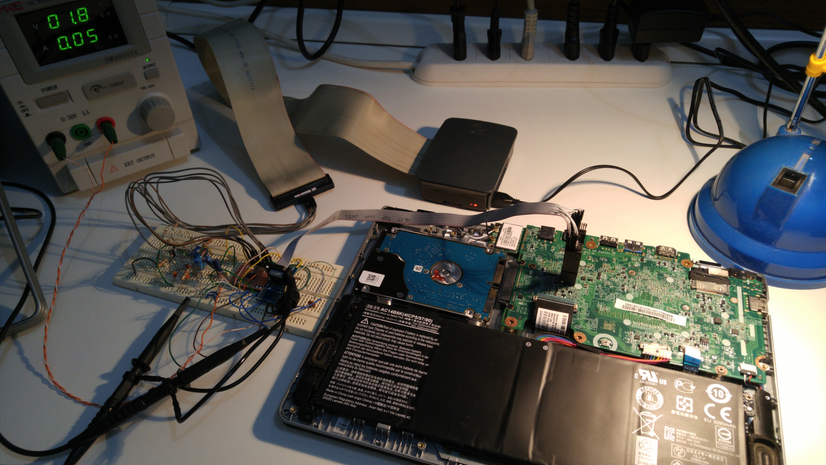
I have connected everything and tried to dump the chip (ignore the left part of the breadboard, it’s an FM transmitter that i did not want to remove but it isn’t powered):
The problem is that i could not dump it! as powering the chip would power other parts of the pc too and turns out that another chip on the pc was keeping the CS (chip select) pin high since it didn’t want to read the chip (unwanted spi bus master). While the raspberry was trying to set it low to read it.
Important note: if you want to try, be sure to have a limited-current power supply because:
- you are powering the bios chip, but probably also other things, and the raspberry might not have enough power to turn on all that things; you might break the raspberry!
- you are powering the pc from the “wrong place” and the bios chip power trace on the pcb is probably small as it is designed to power only the chip, not the whole pc or some parts of it. You risk to burn it and break the pc if the rest of the pc is trying to draw too much current from it.
Part 2: Failing again to dump the chip
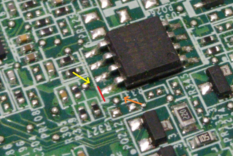
I thought about cutting Vcc line so that the only powered thing was the chip itself, i didn’t want to desolder it for the fear of breaking it.
In the photo you can see a via that goes to another layer (yellow), a trace that is not clear if it is connected on the Vcc line under the chip (orange) and the ideal cut line (red):
The problem is that everything is so small… and the small cutter was huge compared to the chip.
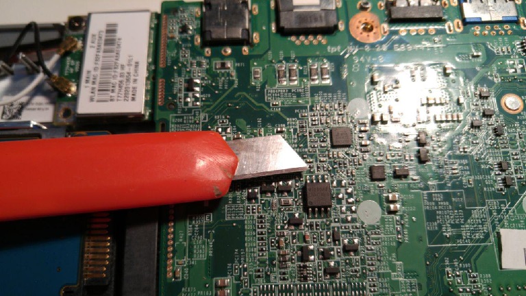
Sure that i would do more damage in trying to cut the trace, i decided to desolder the chip (also because there might be another power trace under the chip).
I then used my raspberry script and dumped the chip.
To be sure that the copy was good i read the whole chip again and hashed the two files but they was different!. DOH!
I have dumped it about 10 times and there was no single good copy.
I have used filter capacitors on the power supply, wires were short, i tried a lower frequency but the problem was still there. I wasn’t sure about the problem…
Part 3: Using a trick to fix the errors
Since the error rate was low, i decided to code a program that would keep, for each byte, the most occurring one: For example if in 10 reads the first byte is 0x12 nine times and is 0x55 only one time i would keep the first byte as 0x12.
Obviously if half reads say 0x12 and other half say 0x55 your result is useless, but this wasn’t the case: the worst case was 7/10 equal.
With this trick i had a good copy that did not give any error/warning in UEFI Tool.
Making the PC boot again
Finding the UUID
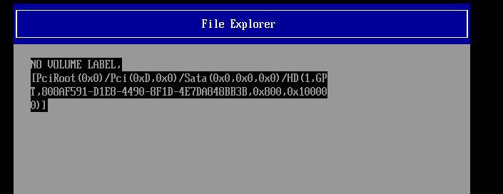
Using UEFI Tool you can navigate to:
Intel image->BIOS region->EfiSystemNvDataFvGuid->VSS store–>Boot0000.
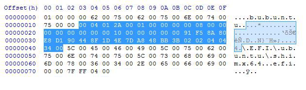
According to Wikipedia: GUID Partition Table the Unique partition GUID has a size of 16 bytes and according to the note d only the first three part are little endian thus has the byte order swapped.
I couldn’t find a way to decode the efi variable but:
going back to the screenshot: the beginning it’s obviously the shown name “ubuntu” in unicode.
The last part is the file to boot.
The central highlighted part is where the UUID can be.
Initially i planned to make many partitions with the UUID set as the bytes [0-15] of the highlighted part, another partition with bytes [1-16] and so on… for the whole highlighted part.
But after installing ubuntu in virtual box and checking the UUID, the first bytes were equal so i found out the correct offset.
The hex dump of the UUID is:
91 F5 8A 80 E8 D1 90 44 8F 1D 4E 7D A8 48 BB 3B
and after fixing the endianess we find out that the partition UUID that the bios is trying to boot is: 808AF591-D1E8-4490-8F1D-4E7DA848BB3B
Changing the partition UUID
We now have the UUID that the pc is trying to boot, so i reinstalled ubuntu on another pc using the notebook HDD and then changed the UUID to match the correct one.
Internet suggest that this command can be used to change the UUID:
tune2fs /dev/sda1 -U 808AF591-D1E8-4490-8F1D-4E7DA848BB3B
But it throw error because it doesn’t support FAT partitions (efi system partition is FAT32)
So i found out this other command that worked
sgdisk -u 1:808AF591-D1E8-4490-8F1D-4E7DA848BB3B /dev/sda
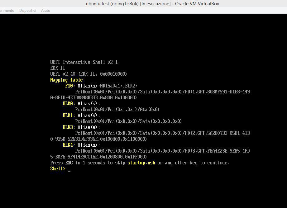
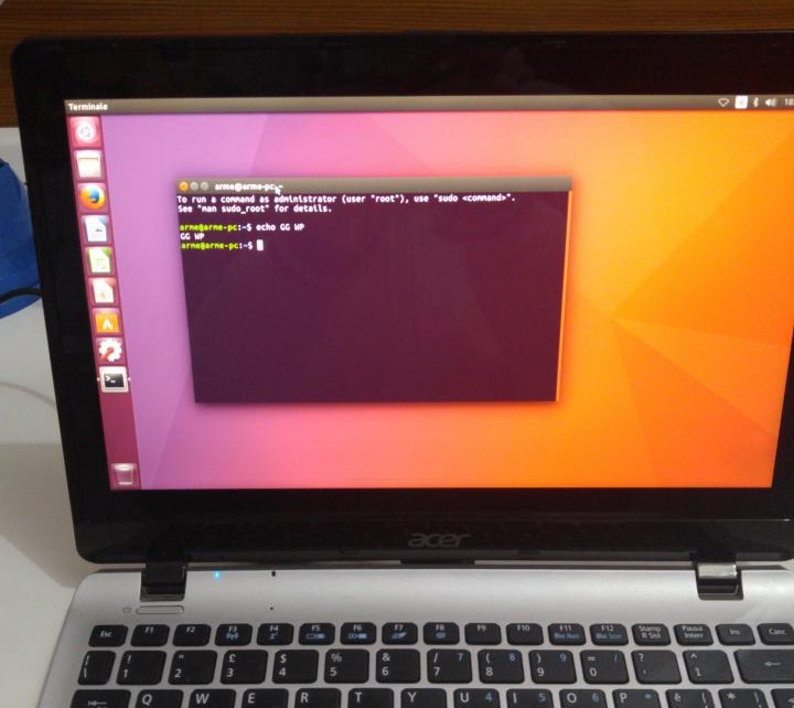
I also have done a quick test on virtual box to see if changing the UUID prevented the virtual pc from booting and turns out that after changing the UUID the pc doesn’t boot but the virtual box bios is a lot better and it gives you a shell:
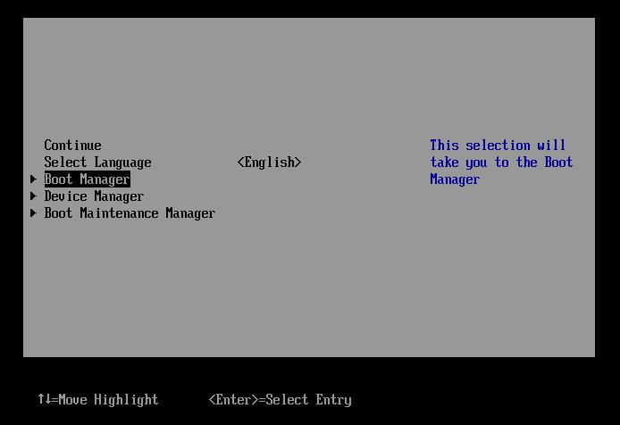
By pressing esc you get this nice menu, so you open boot manager
Select add boot option
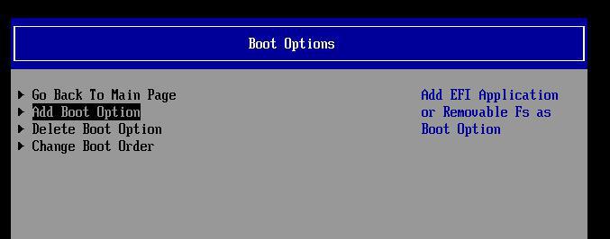
And confirm the new partition.
And yes, i have tried pressing esc in the bricked pc, but it just swapped between “nothing bootable press ok” and “what do you want to boot?” menu.
If the bios was coded a bit better i could fix that pc in 5 minutes.
Anyway this confirmed my theory, so i resoldered the bios, attached the HDD with the corrected UUID and turned it on hoping that my initial idea was correct.
It worked!!! :)
Now everyone is happy, i can give the pc to my friend and get hella cash right?
NO! because he initially planned to install windows and bios wasn’t accessible yet…
My personal war against the bios wasn’t over ;)
Accessing the bios
First tests
Now that the pc boots, it should be simple to access the bios right? NO!
I managed to boot windows recovery usb key using grub shell.
You can make one by typing “recovery” in the start menu, there should be a voice called “create a recovery unit”, it will make a bootable usb with minimal windows components inside.
From there I than tried to reboot in firmware (didn’t know how to do it from linux but i knew how from windows), but it failed giving a cryptic error.
After some searching i found out a linux command:
Systemctl reboot --firmware-setup
but also this one failed; I also found out that GRUB can do it, you only have to type: fwsetup
This one failed too but it gave me an interesting error: “Failed to set OsIndications”
After some searching i found out that this is an efi variable, that if set to 1 boots the pc in firmware mode instead of normal; this only if OsIndicationsSupported is set to 1 too.
I checked from the running ubuntu the efi var and this was the case, it was supported.
You can view the efi vars from linux by navigating to: /sys/firmware/efi/vars/
So why i couldn’t set the variable?
On the internet some people said that it was because of secure boot, other said that it was fastboot.
I searched for interesting stuff with UEFI Tool and i found out:
- Bios password in clear text inside an “invalid” efi var ¯\_(ツ)_/¯
Maybe friend disabled the password so the efi var has been “deleted” (read: invalidated) - Gif and Jpg decoder, why gif?!?!? i can only imagine how many vulnerabilities it has inside… let’s throw “kiss” philosophy outside the window… what could possibly go wrong?
- Two efi vars: secure boot=1 enforcesecureboot=1
- An efi var: reset factory=0
So my new plan was to write secure boot=0 or try to set that reset factory=1 and see what happens.
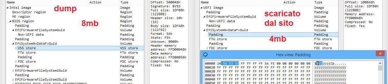
Some friend suggested “why don’t you update the bios?”, is not that simple, the downloaded update was 4mb, while the flash dump image is 8mb because it has ME region and other things; Also, it’s not clear what you should replace: at left you can see the dump that has the VSS store full of the efi vars like the boot one, at right (the downloaded upgrade) that section is simply missing, there is instead some padding.
Writing the SPI flash bios chip
Fixing the reading problem
Now we have a big problem, while we can ignore read errors by reading multiple times and keep the most occurring result, we can’t do the same while writing because spi flash must be erased before writing and the smallest erasable part is a sector of 4096 bytes in size.
On writing we can program it in pages of size 256 bytes. We can’t hope to write 4096 bytes without an error, we have to find out why it wasn’t reading correctly and fix it before continuing.
I decided to use the oscilloscope to check the waveform.
Since it’s an old analog scope it can only show repetitive signals and the spi communication isn’t periodic or repetitive, so i decided to code a small script that kept requesting the device id:
while 1:
  id= f.deviceID()
The communication is not yet periodic, but it is repetitive and can be viewed on the scope, adjusting var holdoff on the scope can help triggering
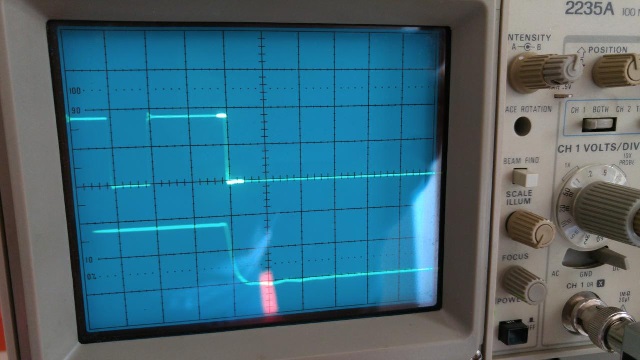
The brighter part is the one zoomed down where you can see the falling edge not perfectly vertical (which is normal, as the components are not ideal).
Anyway, as you can see the signal is “clean”, there isn’t any noise, the circuit is fine, every wire is connected, there are two capacitors: one of 47µF and the other 100nF for each power line; you can find more about why the capacitors here: A practical guide to high-speed PCB layout
To keep it simple, the big one is an “energy store” to smooth lower frequencies, the small one is there to cut away higher frequency noise to/from the voltage level shifter chip.
Here you can see the internal of the TXB0108 voltage level shifter:
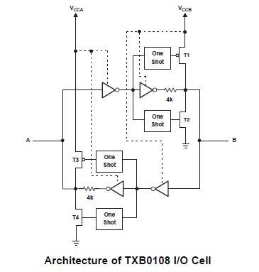
The datasheet says:
For proper operation, the device driving the data I/Os of the TXB0108 must have drive strength of at least ±2 mA.
TXB0108 should not be used in applications such as I2C or 1-Wire where an open-drain driver is connected on the bidirectional data I/O.
To better find out what was causing the problem i decided to rewire the whole circuit and make a simple test program, the idea was:
- To generate a square wave from the raspberry
- Send it to the IC to be shifted from 3,3V to 1,8V
- Connect this signal to another I/O pin to be shifted back to 3,3V
- Read the signal with the raspberry
If everything works both should be identical, this is also a periodic signal that i can analyze more easily with my analog oscilloscope and i can follow it through every step to find out where the problem is.
while 1:
  GPIO.output(OUT_PIN, GPIO.HIGH)
  sleep_ms(waitVal) #ensure that the state is changed
  if (GPIO.input(IN_PIN)!=1):
    print(str(time.clock_gettime(1))+'  e1')
  sleep_ms(ms) #clock frequency
  GPIO.output(OUT_PIN, GPIO.LOW)
  sleep_ms(waitVal)
  if (GPIO.input(IN_PIN)!=0):
    print(str(time.clock_gettime(1))+'  e0')
  sleep_ms(ms)
This program makes a square wave, read it back and print any error along with the time so that even if the console is full of errors and start scrolling you can notice it.
After some tests i have found something interesting:
touching the 3,3V side of the wire was enough to fix the problem, also attaching the oscilloscope probe that has an impedance of 10MΩ fixed the problem (impedance depends also from the frequency, but still is quite high and should be “transparent” to the circuit)
The datasheet also say:
Do not recommend having the external pullup or pulldown resistors. If mandatory, it is recommended the value should be larger than 50 kΩ.
Pro tip: DO-NOT-TRUST-THEM, “you don’t need pulldown” they said… but after adding 10kΩ pulldown resistors on the 3,3V side (the raspberry one) the problem was gone.
So much time wasted in searching something different from pulldown resistors because “you don’t need them so that can’t be the problem”…
Why 10kΩ? well that is what i had at home :)
To be sure that everything worked i have read the bios two times: this time the hashes were equal and they also matched the previous copy obtained by keeping the most occurring byte.
Writing
With the read (and write) problem fixed, i could now write to the bios knowing that it would have been written correctly and that i could always revert to a known good state by reflashing the original image.
So i tried to change secure boot flags without success.
After writing and reading the new result i always got the old value, writing wasn’t working.
The GRUB error gave me an idea: it said that it couldn’t write OsIndications, we know that it is an efi variable, so what if the bios was write-protected?
I started reading the datasheet and it’s a big mess, there are security descriptors that can be enabled or not, that can be volatile or not and there are so many different ways to protect it:
Wps (write protect selection) was 0 this means that what is protected is selected by: cmp,sec,tb,bp[0:2], instead of individual block locks.
Here a quick description of the bits:
- complement: invert the protection
- sector protect: select if block protect bits protect 4k sector or 64k sectors
- top/bottom: select if block protect bits protect from top or bottom
- block protect bits: select the addresses to be protected
Sec,tb,bp were 0 too this means that the whole bios was unprotected but! cmp (complement) was set to 1 this means that the whole chip was write protected!!
So we must write the status register 2 and reset the cmp bit, after we will be able to write.
Also don’t forget about WP pin, it must be high, in this way the chip is not hardware-protected.
There is more to be said on the memory protection like the lock until next power cycle, one time programming (not included in this package), … but we will skip this as we have our solution.
I have soldered the bios (again) and this time fwsetup worked!!
but the acer logo was still missing, so i decided to use the standard procedure to update the bios to the latest version (1.37) in the hope that it also fixed eventual bugs.
The logo was now present and also cd and usb were now present in the boot menu screen.
Conclusion
I’m happy that i fixed it and that my UUID idea was correct, wowser!
in the end the only needed thing to fix the pc was flip one bit, the cmp bit that protected the whole memory preventing us to open the efi bios.
Things needed to flip that bit? tons of old and new knowledge; two months of work of which one wasted waiting the soic test clip to arrive ‘-_-
I gave the pc back to my friend that finally gave me hella cash
a thanks.
I don’t want you to think that he is a bad friend, i have done it for fun, not for profit; this was clear to both even before starting. Anyway it was probably anti-economic repair since looong time, in fact multiple people told me so but i don’t care.
It has been a long but funny journey ^_^
Things missing
A logic analyzer :) anyone? <3
I haven’t explored other interesting stuff found in bios like CrisisRecoveryPei, SysPassword, HddPassword, Computrace, A01D2DRecoveryDriver …
It would be nice to know which is the correct way to use the crisis disk as internet is full of different program versions and opinions like “works only on floppy, even usb floppy but must be floppy”, “i have done it with usb key”, “maybe is the wrong program version”, “fat, not fat32”, …
Also D2DRecovery, usually notebooks has a hidden partition from which you can reinstall windows and there is a special key to boot that instead of the normal partition. In this case the partition have been ereased but maybe there was a way to boot something anyway, after all the error message asked to insert a “recovery media”, whatever is it…
Another missing thing is removing intel ME; we were thinking about trying to remove it but in the end the pc was working and we haven’t tried.
Other thing that i did not try is to backdoor the bios, computrace module was there but there was no option to enable or disable it, nothing in the bios that indicated it’s presence. It would be nice to replace the dropped exe with a custom one, having ssh in case someone steal the pc might be useful. Basically, the pc was working and we did not test anything else.
But perhaps the most important question is: What caused this?
It can be a simple stupid bug, but i like to think that it was because of cosmic rays that flipped the protection bit.
I don’t want to think that i worked for a month because of a dumb person that can’t do his job properly; ok it was funny but still vbox bios was a 1 min solution
Lessons learned
- People should code better bios.
- The efi var OsIndications is used to access the bios, apparently also if you press F2 key.
- Most of the efi vars are “mounted” read-only by linux because some are not standard and erasing or modifying them can brick the pc.
- Without the bios chip if you turn on the pc absolutely nothing happens, not even a led or a fan.
- I couldn’t find the fastboot option in the original bios so maybe my friend was wrong, anyway never enable it! i have read only negative things about it.
- Some people are bugged:
Expected behavior: People say “wow nice findings, thanks for sharing it can be useful, how did you do xyz?”
Actual behavior: Some people started kidding me by answering any asked question by any person in the computer group with “you have to desolder the bios” (like: how do i defragment hdd? you have to desolder bios!).
Anyway, since i have better things to do than caring about such people i decided to set this bug as won’t fix ¯\_(ツ)_/¯ - Pressing fn+tab while in the bios, save and exit, reopen bios, unlocks a “secret” menu full of advanced things (backdoors everywhere)
- Looks like that this wasn’t the only case, see: I think I just bricked my firmware
He was lucky that F12 (probably) showed him the boot menu so he selected usb key and solved, of course i tried the insyde bios recovery guide without success. - Do not mess with uefi if possible, seems full of bugs that will brick your pc. Want to change OS? stay with legacy bios and mbr unless you need uefi for a specific reason.
- Flash memory has low cost, so there is no need to have an old CMOS RAM memory that is lost if you remove the battery, everything is stored directly on the spi flash chip, which is problematic if you want to clear it. The battery is still there only for the RTC clock
- Well, you have read the article right?
I think that it’s important to document the whole process, not only the solution, the process of finding that solution is equally important if not more.
See you next time :)